


Innovation Building Program
Digital Modeling Plays a Key Role
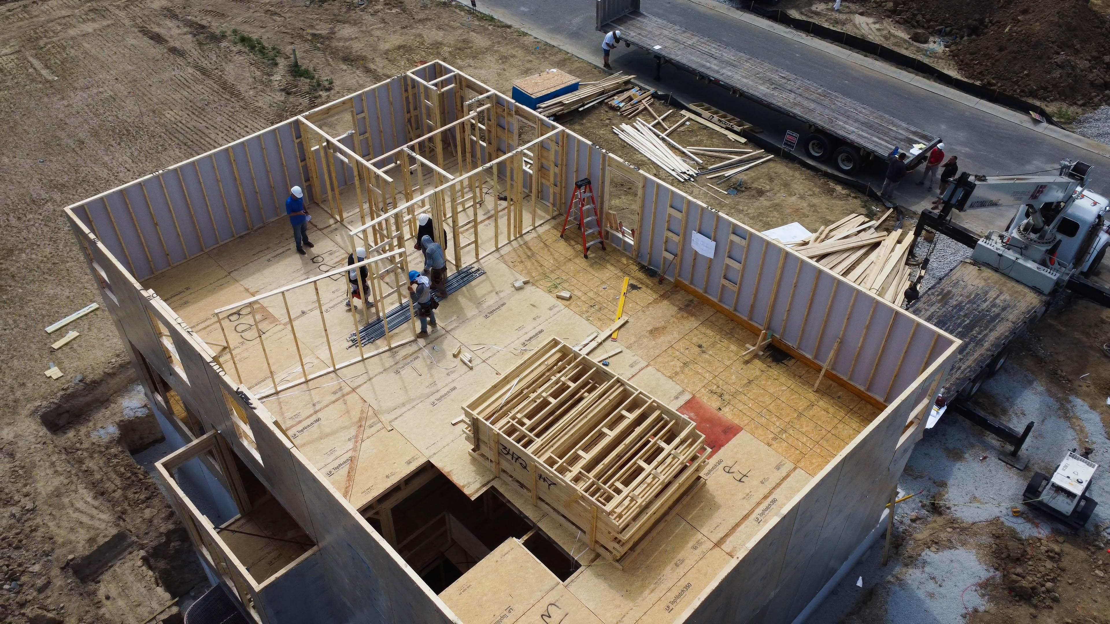
Indianapolis Build 2
Another project within the Innovation Building Program (IBP) is finished, giving MiTek and its partners more data to review and lessons to learn.
Launched in 2021, the IBP seeks to enhance homebuilding methods through collaboration with key partners in the residential construction industry. By adopting a Design, Make, Build (DMB) approach and focusing on components like trusses and panels, the program was created to address housing needs and modernize construction practices, particularly in response to labor shortages and material supply challenges. As interest and investment in the IBP has increased, other groups within MiTek, such as R&D, Services, and Software Innovation, are getting the chance to contribute input.
The team applied the knowledge they gained during the first build to expand the digital modeling on the second project in the Indianapolis Program, incorporating some new architectural designs using software.
Scott Reichensperger, VP of Manufactured Solutions, advocates using a federated model approach to enhance value in innovation programs and beyond. A federated model consists of multiple 3D BIM models, which may include architectural, structural, and mechanical/electrical/plumbing (MEP) components, integrated into a single view to create a multidisciplinary and comprehensive building model.
“The Innovation Building Program has been a learning experience on the digital side,” Reichensperger said. “We look at how digital technology fits into this world, where there’s opportunity for more collaboration early in the design process, and how digital makes homebuilding easier, more efficient, and effective.”
Fast Facts
*Foundation through MEP Rough-In
We look at how digital technology fits into this world…and how digital makes homebuilding easier, more efficient, and effective.
Scott Reichensperger
VP of Manufactured Solutions, MiTek
Reichensperger explained that they collaborated with a builder, architect, HVAC, and plumbing contractors to coordinate the layout of the MEP components, document the installation locations, and prevent collisions with framing components provided by a component manufacturer on the project. The goal was to optimize the use of existing software tools and identify efficiencies in addressing installation challenges virtually.
To achieve this, the team used several programs and platforms to identify the best combination of tools currently available and what future solutions might look like.
“There are many tools available in the industry right now, and as part of the IBP, we’re trying several of them to see which approach makes sense moving forward,” said Steve McFall, SFS Design, Senior Director.
“Ultimately, we’d like to fix those problems within the model there, with everyone watching. Then, we’ll put the federated model in the cloud so it can be accessed remotely by everyone involved,” Reichensperger said.
Traditionally, a builder refers to a set of plans and constructs a house. At different stages of the build process, the builder inspects the progress. They might choose to make changes to the plans as they go. Each time the builder revisits the house plan, they refine the process a little more.
When trades are added to the mix, it introduces another set of challenges. A trade that appears during the build process may notice an error or inconsistency in the design that affects their installation. They might decide to “fix” the problem in the field, as they see fit, without informing the builder or build team. This approach can cause problems for subsequent trades. This snowball effect can lead to increased time and costs that perpetuate if not corrected in the design of future builds.
We’re proposing we do most of the tweaking and changes digitally in an environment where we can see all of the systems work together and can find clashes sooner.
Richard Boothman
Senior BIM Solutions Strategist, MiTek
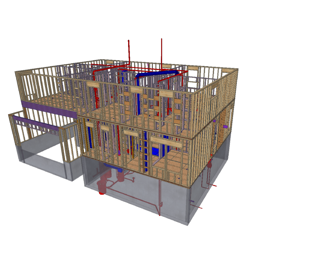
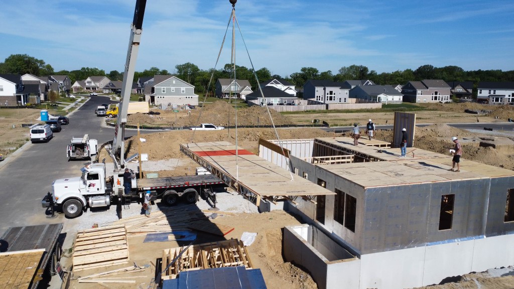
Using a digital solution can streamline the process, even when a builder works with multiple component manufacturers (CM). For example, one CM may build the wall panels, while another builds the roof trusses. By integrating the designs digitally before they arrive on-site, teams can see how the pieces fit together and identify potential problems within the models that would normally only be found in the field during construction and assembly. By catching these problems in the digital model early, they prevent delays during the build on-site.
“We’re proposing we do most of the tweaking and changes digitally in an environment where we can see all of the systems work together and can find clashes sooner,” said Richard Boothman, Senior BIM Solutions Strategist.
Boothman said that viewing the model in 3D offers clearer insight into how connections and systems work together, which enhances communication among the builder, the trades, and even the buyer.
“In a 2D model, a wall is represented as two lines, and a pipe is also shown as two lines,” Boothman said. “If the wall and the pipe intersect, there’s no way to tell if the pipe crosses at the bottom, middle, top, or above the wall. 3D models add depth to show interaction points. We can identify construction issues in the digital format that cost very little to find and would normally cost hundreds of dollars or more in the field to fix or change.”
For the team in Indianapolis, expectations were limited when using 3D modeling during the initial build project because the builder lacked confidence in its effectiveness. By the end of the project, they recognized the advantages of 3D modeling and requested more of it in future builds.
“It’s exciting because, at the end of the day, the goal of the program is for people to learn and then use that knowledge to create a better process for the next build and in a full production environment in the future,” McFall said.
Indianapolis Build 2
Key Takeaways
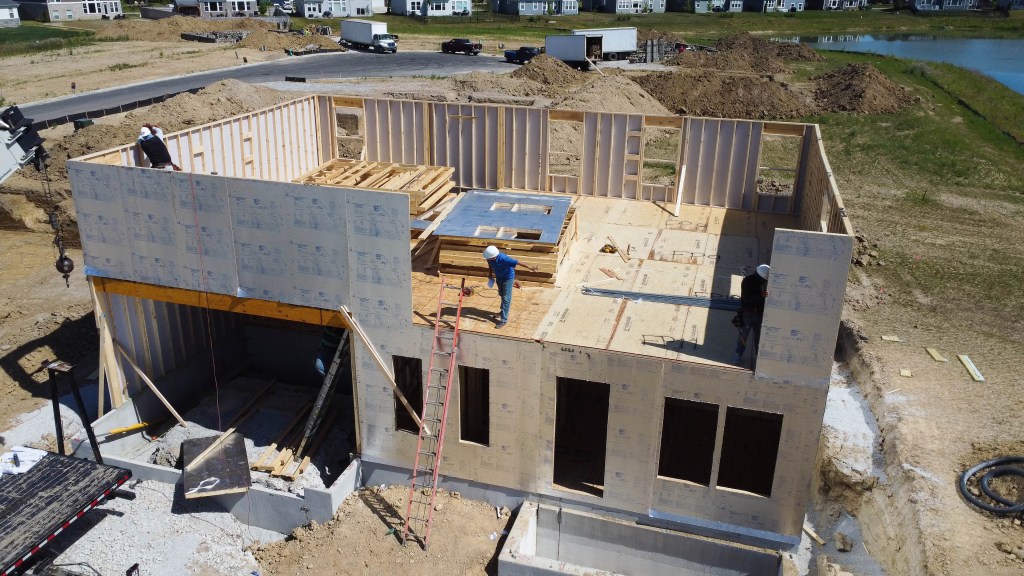
Cycle Time
Rough-in build duration was reduced by 10 cycle days compared to the control build.
Wall panel systems were nearly 50% faster to install compared to stick-framed.
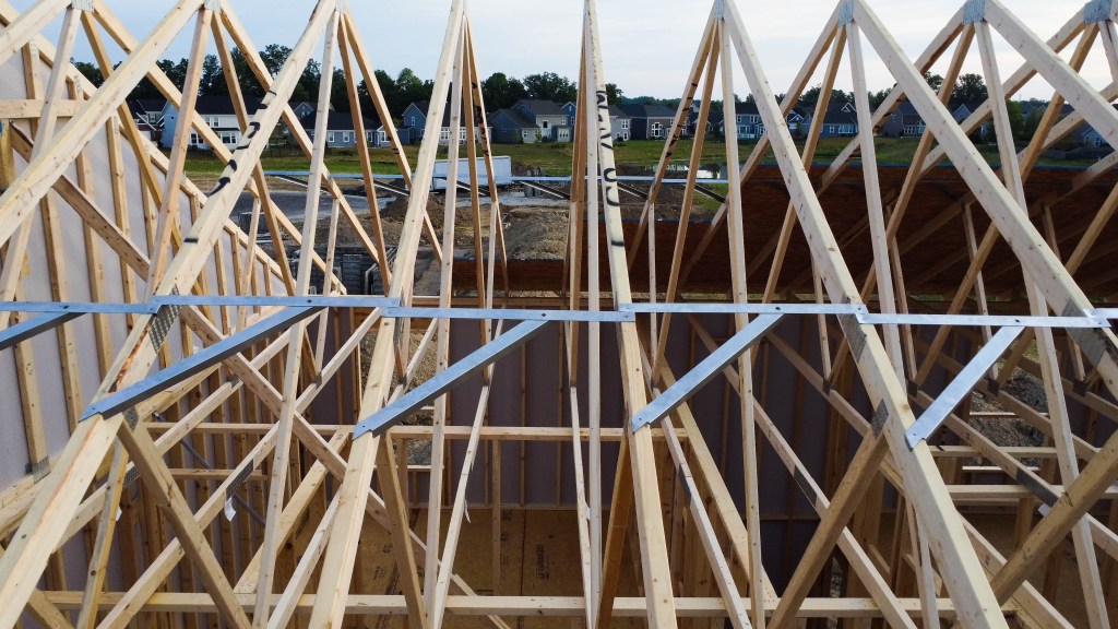
Floor Cassettes were 75% faster than I-Joists.
Productivity Rate
Walls
Innovation Build: 19 linear ft/labor hour
Control Build: 11 linear ft/labor hour
Floors
Innovation Build: 212 sq ft per labor/hour
Control Build: 52 sq ft per labor/hour
The cycle time savings above apply to this build only. Actual results will vary with each project. Learn more about typical whole home componentization savings results.